 Industrial Sensors
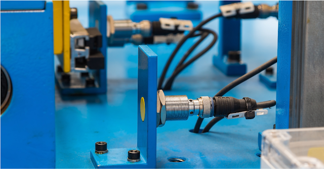
Industrial Sensors | Types & Applications
Industrial sensors are the hidden heroes of modern automation systems, providing rea…

 Industrial Sensors
Industrial sensors are the hidden heroes of modern automation systems, providing rea…

In the world of Electrical, Instrumentation, Control, and Automation (EICA) , unexpe…
 Industrial Automation
In today's rapidly evolving industrial landscape, Automation Engineering is revol…
 Motor Control
When we want to start three-phase induction motors, choosing the right starter is impo…
 Instrumentation
In the world of industrial automation , wiring sensors and devices correctly is critic…
 Industrial Automation
In electronics and data communication, two primary methods are used to transfer data: …
 Maintenance Engineering
Pneumatic System 1. Introduction to Pneumatics Definition : Pneumatics is …
 Motor Control
In the world of automation, robotics, and CNC machinery, choosing the right…
 PLC Programming
A Programmable Logic Controller (PLC) is an industrial computer used to control manuf…
Industrial Sensors
Industrial sensors are the hidden heroes of modern automation systems, providing rea…


