Posts

Showing posts from May, 2025

Electrical Schematics | How to Interpret | Beginner’s Guide

Image
Understanding electrical schematics is a foundational skill for anyone working in electrical, instrumentation, control, or automation (EICA). Whether you're troubleshooting a machine, designing a panel, or programming a PLC, the ability to read and interpret these diagrams is essential. What Is an Electrical Schematic? Schematic Diagram – Shows the functional connections (used for troubleshooting and design). Wiring Diagram – Shows physical connections, cable routing, and terminal numbers. Single-Line Diagram (SLD) – Simplified view, mostly for power distribution. P&ID (for instrumentation) – Shows process, piping, instruments, and control systems. Step-by-Step: How to Read a Schematic 1. Understand the Layout Schematics usually flow left to right or top to bottom . Power supply is often on the left or top. Loads (motors, solenoids, relays) are placed on the right or bottom. 2. Learn the Symbols You’ll need to recognize IEC or ANSI symbols for: Power sources (batteries...

Industrial Sensors | Types & Applications

Image
Industrial sensors are the hidden heroes of modern automation systems, providing real-time data for accurate control, monitoring, and decision-making. Whether you're working with PLCs , SCADA systems , or IoT platforms , understanding sensors is essential. 1. Proximity Sensors Purpose: Detect the presence or absence of objects without physical contact. Types: Inductive: Detects metal objects using electromagnetic fields. Capacitive: Detects both metal and non-metal objects, like plastic or liquid. Magnetic: Uses a magnetic field to detect objects with magnets. Applications: Object detection on conveyors. Position sensing in assembly lines. Bottle counting in packaging. 2. Photoelectric Sensors ...

Maintenance Strategies to Minimize Downtime

Image
In the world of Electrical, Instrumentation, Control, and Automation (EICA) , unexpected failures can lead to costly downtime, production losses, and safety hazards. Implementing effective preventive maintenance can help minimize down time and optimize system performance. 1. Implement a Preventive Maintenance Approach  Use thermal imaging, vibration analysis, and motor condition monitoring to detect early signs of equipment failure.  Leverage IoT sensors and SCADA systems to track real-time equipment health.  Schedule maintenance based on actual equipment conditions rather than fixed intervals. Example: Using infrared thermography to detect overheating in electrical panels before a major failure occurs. 2. Standardize Inspection & Maintenance Checklists ...

Introduction to Automation Engineering

Image
In today's rapidly evolving industrial landscape, Automation Engineering is revolutionizing how businesses operate. It blends electrical systems , instrumentation , and control technologies to improve productivity, accuracy, and safety in manufacturing and process environments. Whether it's a food processing plant, an oil refinery, or a smart factory, automation is the backbone of modern industry. What is Automation Engineering? Automation engineering involves designing and implementing control systems that operate machines and processes automatically , with minimal human intervention. These systems ensure: High-speed production Consistent product quality Real-time monitoring and control Overview of Key Components Electrical Systems These supply and manage power to machines and devices. Power distribution units Circuit breakers and relays Motor control centers Variable Frequency Drives ( VFDs ) Instrumentation Systems These systems measure and monitor physical quantities. Sen...

DOL Starter vs Star-Delta Starter: Key Differences, Working Principles & Applications

Image
When we want to start three-phase induction motors, choosing the right starter is important for ensuring performance, safety, and equipment lifetime. Two of the most commonly used motor starters are the Direct-On-Line (DOL) starter and the Star-Delta starter . In this post, we’ll talk how each one works, their pros and cons, and when to use them—so we can make a better decision for our application. What is a DOL Starter? A Direct-On-Line (DOL) starter is the simplest and most economical method for starting a motor. It connects the motor terminals directly to the power supply. Working Principle When the DOL starter is used, full line voltage is applied to the motor. The motor draws a high starting current (typically 6-8 times the full-load current). It includes protection features like overload relays and fuses. Advantages Simple design and operation. Cost-effective. Easy to install and maintain. Disadvantages High inrush current Not suitable for motors above 5 HP or sensitive electri...

Sinking vs Sourcing Explained: What's the Difference?

Image
In the world of industrial automation , wiring sensors and devices correctly is critical for system functionality and safety. One fundamental concept that often confuses beginners is the difference between sinking and sourcing . These terms define how DC devices like sensors, actuators, and PLCs (Programmable Logic Controllers) handle current flow. What is Sourcing? Sourcing (often associated with PNP devices) refers to when a device supplies current to a load. The output terminal is connected to positive voltage (+V) , and the current flows out of the device into the load, which is connected to ground (0V) . Key Characteristics of Sourcing: Current flows out of the device Output provides +24V (or other DC positive voltage) Typically uses PNP transistors Load connects to GND Example: A PNP proximity sensor is sourcing if it outputs +24V when triggered and connects to a PLC input that is internally tied to 0V. What is Sinking? Sinking (commonly associat...

Serial vs Parallel Communication: Differences & Where to use

Image
In electronics and data communication, two primary methods are used to transfer data: Serial Communication and Parallel Communication . Understanding how each works will help you design better systems, choose the right interface, and troubleshoot more effectively.   What is Serial Communication? Serial communication transmits data bit by bit over a single channel. This approach reduces wiring complexity and is highly reliable over longer distances. 🔌 Common Examples: USB (Universal Serial Bus) RS-232 / RS-485 Benefits: Fewer wires (simpler design) Cost-effective Ideal for long-distance transmission Minimal crosstalk and interference What is Parallel Communication? Parallel communication sends multiple bits at the same time , typically using 8, 16, or more wires in parallel. It’s faster for short distances but less efficient over longer cables due to signal timing issues. Common Examples: Parallel Port (LPT port, IEEE 1284) PATA (Parallel ATA) Data buses ...

Pneumatic System | Beginner's Guide

Image
  Pneumatic System 1. Introduction to Pneumatics Definition : Pneumatics is the use of compressed air to transmit and control energy. Basic Principle : Compressed air is used to do mechanical work, typically by actuating cylinders or motors. 2. Key Components of Pneumatic Systems Compressor – Generates and supplies compressed air. Air Service Units – Includes filters, regulators, lubricators. Actuators – Convert air pressure into motion: Linear actuators (e.g., pneumatic cylinders) Rotary actuators Valves : Directional Control Valves (e.g., 3/2, 5/2 valves) Flow control valves Pressure control valves Tubing and Fittings – For air delivery. Sensors and Switches – For position and pressure feedback. 3. Working Principle Compressed air is stored in a reservoir. Valves direct the air to actuators. Actuators convert pressure into motion . Exhaust air is released to the atmosphere. 4. Advantages of Pneumatics Clean and safe (no sparks...

Stepper Motor vs Servo Motor

Image
  In the world of automation, robotics, and CNC machinery, choosing the right motor is crucial. Two popular types are the stepper motor and the servo motor . While both are used for precise motion control, they differ significantly in performance, cost, and complexity. This guide will help you understand the difference between stepper motor and servo motor , so you can select the best option for your specific application. What is a Stepper Motor? A stepper motor is an electromechanical device that moves in discrete steps. It rotates in fixed increments, which makes it ideal for applications that require precise positioning without feedback systems. Key Features of Stepper Motors: Moves in fixed steps (e.g., 1.8° per step). Open-loop control (no feedback needed). High torque at low speeds. Simple to control using stepper drivers. Best for low-speed, high-precision applications . What is a Servo Motor? A servo motor is a closed-loop system that uses feedback...

What is a PLC | How it Works | Architecture

Image
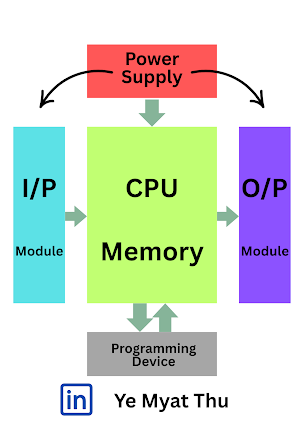
A Programmable Logic Controller (PLC) is an industrial computer used to control manufacturing processes, machinery, or automation systems. PLCs are rigid for harsh environments and are programmed to perform logical, sequential, and timed operations. Whether you're operating an assembly line or managing a water treatment plant, PLCs are behind the scenes making things work smoothly and automatically. PLC Architecture At the heart of every PLC lies its architecture. Here's how it's typically structured: 1. Central Processing Unit (CPU) This is the brain of the PLC. It processes inputs, executes the control program, and sends output signals. The CPU includes memory for program storage and execution. 2. Input/Output (I/O) Modules Input modules receive signals from sensors, switches, or buttons. Output modules control devices like relays, valves, and Magnetic Contactor(MC). 3. Power Supply Supplies the required DC power to the CPU and other components. 4. Programming Device E...

Current Transformer vs Potential Transformer | Key Differences

Image
  In electrical power systems, measuring voltage and current accurately is crucial for safety, monitoring, and control. Two essential instruments used for this purpose are Current Transformers (CT) and Potential Transformers (PT) , also known as Voltage Transformers (VT) . Though both are types of instrument transformers, they serve different purposes. In this blog, we’ll explore the key differences between Current Transformers and Potential Transformers , their working principles, and where they are typically used. What is a Current Transformer (CT)? A Current Transformer (CT) is a type of instrument transformer used to measure high currents in a circuit by stepping them down to a lower, manageable value that standard instruments can handle. Key Features of CT: Used for current measurement . Secondary current is usually 5A or 1A . Connected in series with the power circuit. Provides isolation and protection for measurement devices. Ideal for over current pr...

Variable Frequency Drive (VFD) | Working Principle | Applications

Image
In today’s industrial automation landscape, energy efficiency and precise motor control are more important than ever. A Variable Frequency Drive (VFD) plays a vital role in achieving both. Whether you're a maintenance engineer, automation technician, or facility manager, understanding VFDs can help you save energy, reduce costs, and improve performance.   What is a Variable Frequency Drive (VFD)? A Variable Frequency Drive (VFD) is an electronic device that controls the speed and torque of electric motors by varying the motor input frequency and voltage. By adjusting the power supplied to the motor, a VFD ensures optimal performance for different load conditions. How Does a VFD Work? A VFD operates in three basic stages: Rectifier Stage: Converts incoming AC power to DC. DC Bus: Smooths the DC power using capacitors. Inverter Stage: Converts DC back into variable-frequency AC power to control the motor. This variable output allows precise control of motor speed and t...